Diagram View: General Information
In addition to using the Workflow (Tree View) page, you can use the Workflow (Diagram View) page (also referred to as the Workflow Visual Editor) to work with a particular workflow.
Learning Objectives
In this chapter, you will learn about the use of the Workflow (Diagram View) page to customize workflows.
Applicable Scenarios
You use the Workflow (Diagram View) page to create or modify workflows if you prefer to use a visual representation of a workflow instead of its tree view.
Working with the Diagram View
The diagram view is structured like a traditional workflow, with visual representations of the states of the record and the transitions between them. To access the diagram view, while you are working with the tree view of the particular inherited, custom, or predefined workflow on the page, you click Diagram View on the page toolbar.
If you want a record on a form to have a status that is not available in an out-of-the-box system, you add a state that represents this status. If you want to indicate to the system that the status of the record should change when a user invokes a particular action, you specify this action as a trigger for the transition.
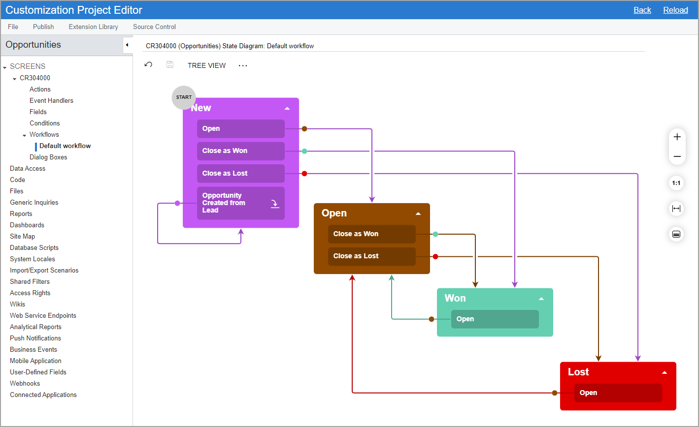
In the diagram view of a workflow, different states of the workflow are represented by boxes of different colors, and actions and event handlers that trigger transitions between the states are represented by labels in the boxes with states. The labels appear after you create a transition and specify the source and target states.
You add transitions from one state to another by drawing lines between these states. To draw a line, in the box with the initial state, you click and hold the plus button. When you add a transition, you need to specify an action that triggers it. You can select an existing action or add a new one.
The following screenshot shows the Workflow (Diagram View) page for the Opportunities workflow. Notice that the page name is CR304000 (Opportunities) State Diagram: Default Workflow. The form number and its name (in parentheses) precede State Diagram, which is followed by a colon and the workflow name of the predefined workflow (Default Workflow in this case).